
Before installing a hydraulic cargo lift, confirm the maximum load, cargo dimensions, floors served, and available space. These details guide the lift configuration and requirements for clearance, foundations, structural support, and power. Finalize the installation plan using a site assessment and the manufacturer’s project-specific drawings, while checking applicable local safety and approval requirements.
Confirm the Lift Specifications and Installation Type First
Installation planning begins with how goods will move through the building. The weight and dimensions of the goods guide the lift’s capacity and platform size, while the floors served and the height between them establish the required vertical travel. If goods enter from one side and leave from the opposite side, the lift may need a different door arrangement than it would for same-side loading and unloading. The lift must also fit the building, so the loading route and site conditions should be considered before its configuration is selected.
For a preliminary layout, provide the manufacturer with:
- Load and cargo size: Provide the maximum combined weight of the goods, pallets, and any handling equipment on the platform, plus the dimensions of the largest load. If wheeled equipment will enter the platform, identify its type so the manufacturer can assess its effect on platform loading.
- Travel: The floors to be served and their floor-to-floor heights.
- Loading route: The entry and exit sides at each landing and how goods are moved onto the platform.
- Site conditions: Whether the lift will be installed indoors or outdoors; the available width, depth, and overhead clearance; existing shafts or floor openings; and any known limits on pit construction. Include plans or photos if available.
The manufacturer can use this information to propose the rated capacity, platform size, door arrangement, and installation type. The proposed layout then becomes the basis for checking the space, structural, electrical, and safety requirements discussed below.
1. Space and Clearance Requirements
After the manufacturer proposes a preliminary layout, use site measurements to check the following space requirements and identify any changes needed to the layout.
Equipment Footprint
The platform itself is only part of the space needed for the lift. Compare the available width and depth at each level with the preliminary layout, which includes the guide rails, any enclosure, and planned landing doors.
Floor Openings
If the lift passes through floors, check the position and clear dimensions of each existing or proposed opening against the preliminary layout. Record any differences between existing openings and the proposed dimensions before the layout is finalized. For an example of this layout, see the floor-opening hydraulic cargo lift.
Overhead Clearance
At the highest landing, check that the available height can accommodate the lift at its highest position while leaving the overhead clearance required in the manufacturer’s drawing.
Landing Clearance
At each landing, check whether the entrance width, entrance height, and approach area allow the largest load and its handling equipment to enter and leave in the planned direction. Note any obstructions along the loading route.
Delivery Access
Check the route from the unloading point to the installation location, including building entrances where applicable, corridors, and turns. Compare it with the dimensions of the lift components that need to be transported.
Installation and Maintenance Access
Confirm that the layout leaves room to assemble the lift and reach its service points. Ask the manufacturer to specify the working space needed for installation, inspection, and maintenance.
2. Pit, Foundation, and Structural Support
The preliminary layout must also be checked against the building’s supporting structure and any construction work the installation requires.
Pit or Pit-Free Design
A recessed pit is commonly used when the platform must be level with the floor at the lowest landing so goods can roll directly onto it. With a pit-free, surface-mounted arrangement, the lowered platform sits above floor level, so loading may require a ramp or another suitable method. A shaft or floor opening does not, by itself, determine whether a pit is needed. The manufacturer should confirm the arrangement for the selected lift and loading method in the project drawings.
Foundation and Floor Capacity
Obtain the proposed lift’s support loads and their locations from the manufacturer. A qualified structural professional should then assess whether the foundation, floor slabs, or other supporting elements can carry those loads during use. This check is especially relevant when the lift is supported by an upper floor or mezzanine. See upper-floor installation for an example of a lift supported by an upper floor slab. A pit-free design still requires an adequate supporting structure.
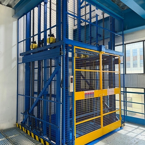
Upper-floor hydraulic cargo lift installation
Floor Openings and Building Modifications
Creating or enlarging a floor opening may affect the surrounding slab and its supports, even when the opening has enough space for the lift. Review the proposed work against the building’s structural drawings and actual site conditions, including any services in the affected area. Have changes to load-bearing elements and any required reinforcement assessed before construction begins.
Guide Rail Supports and Anchor Points
The guide rails keep the platform aligned as it moves between floors. The preliminary drawings should show what supports the rails and where the rails or their brackets will be anchored. Check the proposed supports and fixing details against the manufacturer’s load information and the site’s structural conditions.
3. Power Supply and Hydraulic System
The preliminary plan should identify how the lift will receive power and where the controls and hydraulic equipment will be installed.
Electrical Supply and Protection
Ask the manufacturer for the project-specific supply voltage, phase, frequency, motor power or current demand, and required protective devices. Verify that the site can provide this supply at the planned connection point. Circuit isolation and grounding should be arranged according to the equipment’s electrical drawings and applicable local rules.
Controls and Cable Routing
Identify the locations of the control cabinet and the operating stations required at the landings. Plan cable routes between the cabinet, hydraulic power unit, landing controls, and any door interlocks or sensors specified for the lift. Fixed wiring may be concealed or installed in conduit. Any exposed cables should be routed and protected against damage from moving lift parts, goods, or handling equipment. Cable specifications and connections should follow the manufacturer’s electrical drawings.
Hydraulic Power Unit and Piping
The hydraulic power unit typically includes the pump, motor, and oil reservoir. Confirm its proposed location and allowable distance from the lift with the manufacturer. The hydraulic drawings should show the hose or pipe routes and connection points; check that the lines can be routed and protected without obstructing the lift or landing access.
Service Access and Site Conditions
Reserve access to the power unit and control cabinet for inspection and maintenance. Check temperature, moisture, dust, and ventilation at their proposed locations against the equipment requirements. For outdoor or water-exposed locations, confirm that the specified equipment and enclosures are suitable for those conditions.
4. Safety Measures and Local Approvals
Before site work begins, confirm the selected lift’s guarding, safety functions, intended use, and local approval requirements.
Landing Doors and Enclosures
The project drawings should show how each landing and exposed side of the lift’s travel path will be guarded. Where there is no fully enclosed shaft, separate barriers may be needed. The drawings should also show how the landing-door interlocks prevent lift movement when a door is open and keep the door closed when the platform is at another landing, including where the interlock components and control wiring will be installed.
Operating Safety Devices
Ask the manufacturer for the safety functions specified for the selected lift, such as travel limits, emergency stopping, overload protection, and protection against unintended movement or descent. The control and hydraulic drawings should identify the devices that perform these functions. Their design depends on the lifting mechanism and applicable local requirements.
Intended Use
Confirm whether the selected equipment is specified for goods-only use, and ensure its rated capacity and loading instructions match the intended operation. People must not ride a goods-only lift. If people need to travel with the goods, tell the manufacturer before equipment selection and check the applicable approval requirements.
Qualified Installation and Site Safety
Arrange installation by personnel qualified for the mechanical, electrical, and hydraulic work involved. During installation, guard open floor penetrations and restrict access to the work area. Follow the manufacturer’s project drawings and installation instructions.
Permits, Rules, and Inspections
Before construction, ask the local authorities whether permits are needed for the building changes, electrical work, and lift installation. Check separately whether installers need a local license and whether the lift must be inspected or approved before use. These requirements depend on how the lift is classified locally. Record the answers in the installation plan.
Testing and Acceptance Before Use
After installation, check that the lift travels and stops correctly at each landing. Complete no-load and load tests as specified in the project’s commissioning plan. Verify the safety functions provided for the selected lift, including landing-door interlocks, emergency stopping, and travel limits. Inspect mechanical fixings, electrical connections, and hydraulic lines and fittings for defects or leaks. Correct any problems and repeat the affected checks.
Before regular cargo service begins, complete any locally required inspection or approval, obtain the test records, final equipment drawings, and operating and maintenance instructions, and ensure operators receive training. For more on this stage, see the commissioning and acceptance guide.
Conclusion
Installing a hydraulic cargo lift requires project-specific checks of space and clearance, pit and structural support, power and hydraulic arrangements, and safety and local approvals. Share the maximum combined load, largest cargo dimensions, floors served and floor-to-floor heights, plus site plans and photos, so the manufacturer can prepare a preliminary layout for site review. For an overview of common installation methods, see the hydraulic lift installation guide. For help selecting a lift, visit our hydraulic cargo lift range and contact us with your project requirements.
Frequently Asked Questions
Does every hydraulic cargo lift need a pit?
No. A pit is commonly used when the platform needs to be level with the floor at the lowest landing. Without a pit, the platform may remain above floor level when lowered, so a suitable loading method, such as a ramp, must be considered. Confirm the arrangement in the selected lift’s project drawings.
Can a hydraulic cargo lift be installed in an existing building?
It may be possible. Assess the available space, structural support, power supply, and whether any required floor openings or other building changes are feasible. Local approval requirements must also be checked.
How are the installation dimensions determined?
The manufacturer prepares a preliminary layout from the load, cargo size, travel, loading directions, and site measurements. Check the full equipment footprint, floor openings, overhead clearance, and landing access against that layout. Use the project drawings for the final dimensions rather than calculating them from the platform size alone.
What should I provide to get an installation layout?
Provide the maximum combined weight of the goods, pallets, and any handling equipment on the platform; the largest cargo dimensions; the floors served and their floor-to-floor heights; and the entry and exit sides at each landing. Include plans or photos showing available space, existing openings, and any limits on pit construction.